Welcome to Vintage Radio Emporium
Welcome! Step into a world where vintage charm meets modern sound. Here, you’ll find everything from classic radio collectibles to insights on today’s beautifully crafted reproduction models. Explore, enjoy, and discover the best of radio history and innovation.
ESTABLISHED 1998
★★★★★
Discover Vintage Radio Treasures
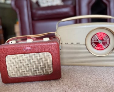
Vintage radios have a timeless charm, adding a nostalgic touch to any space. However, they often lack the audio clarity and modern features we rely on today. For those who admire the classic look but seek improved sound quality and convenience, reproduction radios offer the best of both worlds—vintage style with contemporary performance. Discover more about these modern takes on timeless designs and bring the beauty of yesterday into today’s listening experience.
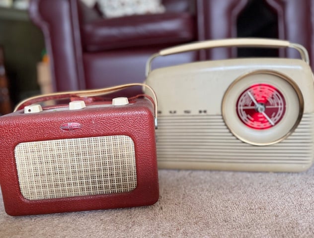
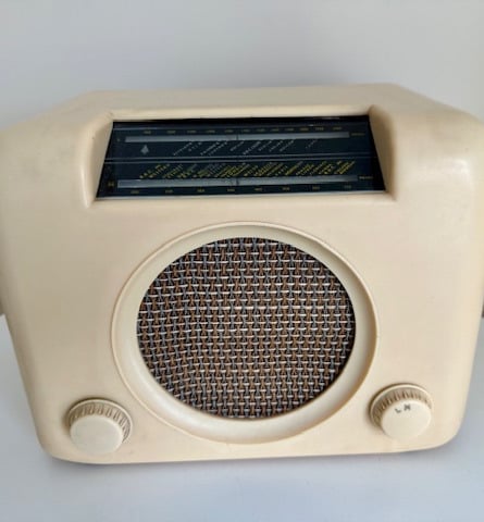
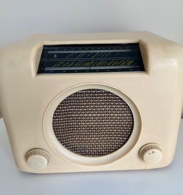
Vintage Radio
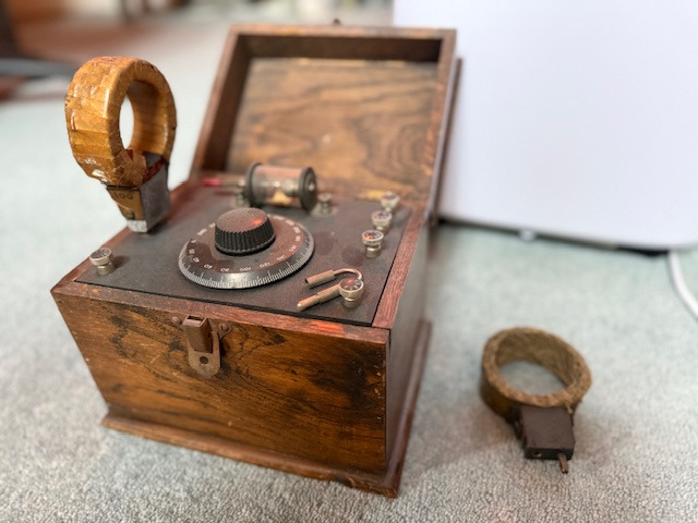
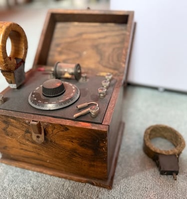
Explore our unique collection of vintage radios and crystal sets from the past.

Discover rare vintage radios and crystal sets, lovingly curated for enthusiasts.
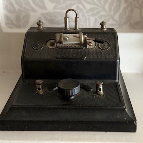
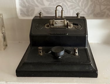
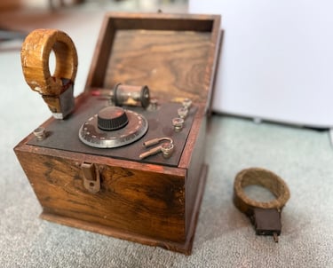
Origins
The original website dated back to 1998, and has been lost in time.
The first radios people had at home, often homemade.
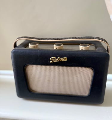
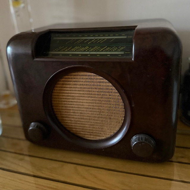
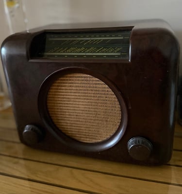
Vintage Treasures
Explore our curated collection of classic radios from the past.

The Vintage Radio Emporium is a delightful journey back in time. The collection of crystal sets is impressive.
★★★★★
Nostalgia
Explore our collection of vintage radio treasures.
CONTACT
radio@qsy.to
© 2024. All rights reserved.
Sign up to receive occasional updates about vintage radios, including news, trends, and special features.